Thursday, February 28, 2013

VHDL: Rules for Variables and Variable Use

Variables are objects used to store intermediate values between sequential VHDL statements.
Variables are allowed only in processes, functions and procedures and are always local to them.
Variables are much like variables in conventional software programming language.
They immediately take on and store the value assigned to them.

Variables are commonly not understood and are therefore not used much.Variables can be
very powerful when used correctly. Here we explain on how to properly use variables. Variables are used to carry combinatorial signals (when used properly, otherwise they can infer sequential logic also) within a process.Variables are updated differently than signals in simulation and synthesis.

In simulation, variables are updated immediately, as soon as an assignment is made.This differs from how signals are updated in simulation. Signals are not updated until all processes that are scheduled to run in the current delta cycle have executed. A variable can be used to carry a combinatorial signal within both a clocked process and a combinatorial process.
This is how synthesis tools treat variables – as intended combinatorial signals but the way coding is done can change the synthesis results. Especially, the order in which signal and variable assignments are made results in the difference.

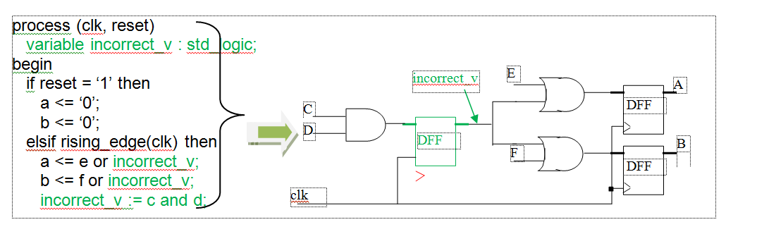
Figure below shows how to use a variable correctly.  In this case, the variable v maintains its combinatorial intent of a simple two-input and-gate that drives an input to an or-gate for both the a and b registers.

Figure:: Correct Use of Variables


In Figure below, you read from the variable incorrect_v before you assign to it. Thus, incorrect_v uses its previous value, therefore inferring a register because that's the only way to have previous value available inside Sequential process. Had this been a combinatorial process, a latch would have been inferred.


Figure:: Incorrect Use of Variables


Conclusion/Rule for variable usage ::
Always make an assignment to a variable before it is read. Otherwise, variables will infer either latches (in combinatorial processes) or registers (in clocked processes) to maintain their previous value.  The primary intent of a variable is for a combinatorial signal. 

Friday, February 22, 2013

FIFO DESIGN ........

FIFO Design is one of the very tricky & critical design problem ...
First question is ......
Q. Why do we require FIFOs in our design ?
A. Answer to this quest. is whereever we need to transfer multi-bit data from one clock-domain to another,
     that too for mostly asynchronous clock domains i.e. whereever asynchronous clock-domain-crossing is
     involved otherwise there can be issues like data Incoherency or data loss.

     Thus, FIFO is basically used to take-in n-bit data say Data In from some block at say ClockA rate
     and then give-out the n-bit data say Data Out to some other block at Clock B rate as shown below.


     Now What are these FIFO Full and FIFO Empty doing in the figure above ?
     ............................................................
     ..............think ...........think ..................

     As we are writing data in this FIFO at some rate and reading data at some other rate, there is always
     a possibility of FIFO getting totally filled with input data. So, in such a case, there should be some way to
     inform the input Block Not to send any more data. FIFO Full signal is just meant for that purpose.
     Similarly FIFO Empty is there to let the receiving block know that there is no more data to be read now.

     Now, How to generate these FIFO Full and FIFO Empty signals correctly ?
     ## This is the most tricky part of the FIFO design. :)
     ## Try to work out on this .... it will open up many things for you ....

     For those who are crazy to quickly know ............
     Consider the below diagram for understanding FIFOdesign precisely ::


Tuesday, February 19, 2013

State Machine Design

Lets consider some sample problems which are best solved by State Machine designs...

1. If we have to design a digital logic to detect the sequence "10" in the input bit-stream ...
2. If Master M wants to communicate with Slave S, then Slave S can recognize the
    Master A out of many  masters by detecting some pattern.
    Let that pattern be Hex "F687" ...
3. If we have to detect the Even/odd No. of 1's in the input bit stream ...
4. If we have say, 5-bit input data and we have to detect the event -> " When the Sum
    of the 5-bit input data  is divisible by 5/7/9 etc "
5. State machines can also be used to generate source data at a rate, such that it is stable for at least
    1 complete cycle of the destination clock

There can be many such Problems in Real Chips which are resolved using State Machine design concepts only or In-addition to other concepts ....

Now, The question is .......

How State Machine design is done ?

1. Step 1 is to identify the No. of states that will be required to implement a state machine.
    This will depend on the kind of state machine you are going to build. For e.g. for
    detecting a sequence of  bits like "10" in the input bit-stream,
    How many states you will require ........?
    ....................................
    ..................................
    Think about it  ...........
     ..................................
     Think, if you can implement with lesser No. of states
     ...................................
     ..................................
2.  Now start from first state. This be the state when system starts after reset.
     Let first state name be = initial
     Conside both 1 and 0 inputs at this state and decide what should happen
     on receiving both the inputs respectively.
     In General, If we are moving closer to fully detect the pattern (means if we have 
     partially detected some part [few bit(s))of the full pattern] then we have to 
     move to the next state, otherwise we have to either stay at the same stay or we 
     have to move back to one state up OR 2 states up OR 3 states up depending on 
     the complete  pattern to be detected. 
    Few examples and some practice will clear this concept concisely.

     Another important aspect of the state machine design is whether we want the 
     output (to indicate PATTERN DETECTED ) to be High during transition b/w
     particular states or just For a particular State.
     This leads us to 2 types of state machines - Mealy OR Moore respectively.
      .........................
      Can you try to find which type of state machine will have more states ?
      ...........................
      ...........................
     
       For the pattern "10" detection, Below is our first state machine :


      Similarly, You can try creating Both Mealy and Moore machines for the examples
      given at the beginning of this topic.
      ## Remember Practice makes the man perfect

       Lets have some more discussion on these two types of state machines ::

       Mealy Machine ::

       - In a Mealy machine, the outputs are a function of the present state and the
          value of the inputs as shown in figure above.
ƒ       - Accordingly, the outputs may change  asynchronously in response to any
         change in the inputs .
          Why Asynchronously ? Think ...........
          Can you think of the kind of the Circuit the mealy machine will have ?
           .....................................
        Moore Machine ::

        - In a Moore machine the outputs depend only on the present state as shown in
           figure below.
        - More states than mealy but output is Synchronous with state
Quests to think about ........

          1. How can we map the states with the actual digital logic design elements ?
          2. Does more states means more logic is reqd. ?